Current In A Parallel Circuit
This is the case with a parallel RL circuit mainly because the output voltage V out is equal to the input voltage V in. In this way we can find the short circuit MVA and current values for any type of network and any type of fault using the simple MVA method quickly and easily.
Simple Parallel Circuits Series And Parallel Circuits Electronics Textbook
Simple Parallel Circuits Series And Parallel Circuits Electronics Textbook
The Difference Between Series And Parallel Circuits Basic Direct Current Dc Theory Automation Textbook
Apply Kirchhoffs voltage law In this equation.

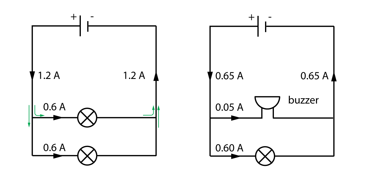
Current in a parallel circuit. The advantage to a parallel circuit is that if one device malfunctions the flow of electricity will not stop as it will in a series circuit. Simple parallel resonant circuit tank circuit. Current divider rule is only applicable for two resistors when many resistors are connected in parallel some other methods will be applied to find each current value.
It is seen that the supply current flows through resistor R 1 and that it splits up into I 2 and I 3 in order to flow through R 2 and R 3. Therefore the current supplied to the circuit is max at resonance. The circuit of figure 2 a is reproduced in figure 4 with the branch currents and voltages identified.
Since we know the equations for determining the reactance of each at a given frequency and were looking for that point where the two reactances are equal to each other we can set the two reactance formula equal to each other and solve for frequency algebraically. The parallel RL circuit is not used as filter for voltages because in this circuit the output voltage is equal to input voltage and for this reason it is not commonly used as compared to series RL circuit. Since the voltage remains unchanged the input and output for a parallel configuration are instead considered to be the current.
The parallel RL circuit is generally of less interest than the series circuit. For example when electronics components such as resistance R1 R2 and R3 are connected in a parallel branch with connected voltage source Vs. The current in the circuit and the voltage everything will remain the same.
In the above parallel RLC circuit we can see that the supply voltage V S is common to all three components whilst the supply current I S consists of three parts. Example of Current Divider Rule. Everything in the circuit will remain the same.
Because the circuit is a combination of both series and parallel we cannot apply the rules for voltage current and resistance across the table to begin analysis like we could when the circuits were one way or the other. The area of the solar cell. Questions 9 and 10 refer to the following.
A 50-ohm resistor an unknown resistor R a 120-volt source and an ammeter are connected in a complete. Consider a RLC circuit having resistor R inductor L and capacitor C connected in series and are driven by a voltage source V. 7-10-00 Section 191 Series circuits.
For f. The short-circuit current depends on a number of factors which are described below. 1 Consider a very simple circuit consisting of four light bulbs and a 12-volt automotive battery.
As a result this circuit does not act as a. Will the fuse melt if the microwave and the coffeemaker are both on. Figure 5 Power components of a RC parallel circuit.
Current in Series-Parallel Circuit. The current is the same through each resistor. Let Q be the charge on the capacitor and the current flowing in the circuit is I.
A 110-V household circuit that contains an 1800-W microwave a 1000-W toaster and an 800-W coffeemaker is connected to a 20-A fuse. An acceptance circuit is defined as when the In the Lt f f0 is the maximum and the impedance of the circuit is minimized. For a parallel configuration the inverse of the total impedance Z RLC is the sum of the inverse impedances of each component.
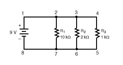
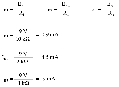
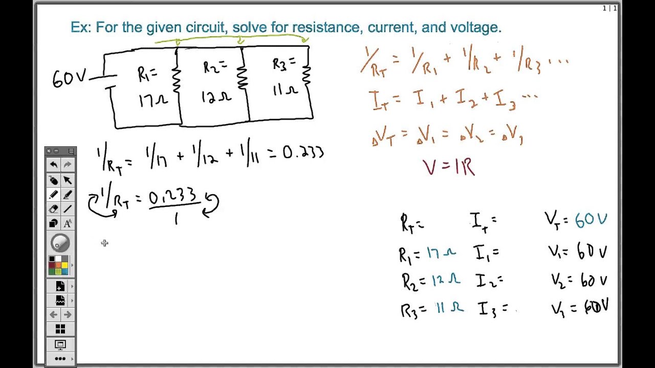
I R the current flowing in the resistor branch in amperes. The three resistors R 1 R 2 and R 3 in are connected in parallel to the battery as shown in Figure. In the parallel circuit connection the number of electrical elements or components are connected in parallel form.
Equation of RLC Circuit. For f -X C. A parallel circuit is one that has two or more paths for the electricity to flow the loads are parallel to each other.
The power components for a parallel RC circuit are illustrated in Figure 5. Power in Parallel RC Circuit. In the above circuit we have a 10 µF capacitor and a 100 mH inductor.
The circuit is more capacitive in nature because the capacitive current is greater than the resistive current. When voltage source is given to a circuit the same. A circuit caring I current and divides across two resistors viz.
In a parallel circuit the electrical current flows along several paths and each individual device is hooked up to its own circuit. Therefore for an ideal current amplifier the current transfer ratio is an important parameter. Short Circuit Current at F2 Total Short circuit MVA up to the fault1000 1732 KV 35381000 173233 619A.
Resistors in Parallel Consider a circuit with 3 resistors in parallel such as the circuit below if N 3. There exists more than one path for current to travel not series yet there are more than two sets of electrically common points in the circuit not parallel. As parallel connection all are independent and takes current as need.
If the loads in this circuit were light bulbs and one blew out there is still current flowing to the others because they are still in a direct path from the negative to positive terminals of the battery. It can be interesting until it is fed by a current source. Thus the circuit is.
A current mirror circuit mirror or copy the input current of one active device to the other active devices output. An ideal current mirror circuit is an ideal current amplifier with the inverting configuration that can reverse the current direction. A series circuit is a circuit in which resistors are arranged in a chain so the current has only one path to take.
Parallel Circuit Problems with Solutions. 10Ω and 15Ω. Current would go down the path of no resistance leaving no current passing through the lamp short circuit.
EE301 - PARALLEL CIRCUITS AND KIRCHHOFFS CURRENT LAW 3 992016 Example. 1Z RLC 1Z R 1Z L 1Z CIn other terms the total admittance of the circuit is the sum of the admittances of each component. Calculate a the potential difference across each resistor b the effective resistance R of the circuit c the current I in the circuit d the currents I 1 I 2 and I 3 passing through each.
So lets go ahead and do that. Determine the unknown currents in the circuit shown below. Series and Parallel Circuits.
At resonance there will be a large circulating current between the inductor and the capacitor due to the energy of the oscillations then. To remove the dependence of the solar cell area it is more common to list the short-circuit current density J sc in mAcm 2 rather. The total resistance of the circuit is found by simply adding up the resistance values of the individual resistors.
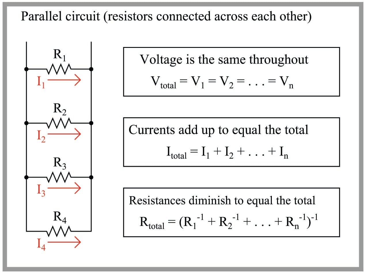
The current flowing through the resistor I R the current flowing through the inductor I L and the current through the capacitor I C. So lets draw the rest of the circuit as it is but replace this combination with a single resistor of eight ohms. In a parallel circuit the voltage across each of the components is the same and the total current is the sum of the currents flowing through each component.
So what well do is Ill keep the rest of the circuit as it is. Therefore the short-circuit current is the largest current which may be drawn from the solar cell. But the current flowing through each branch and therefore each component will be different to.
Since the voltages across all the parallel elements in a circuit are. A parallel circuit containing a resistance R an inductance L and a capacitance C will produce a parallel resonance also called anti-resonance circuit when the resultant current through the parallel combination is in phase with the supply voltage. The formulas that apply are the same as that of a parallel RL circuit.
Resistance inductance capacitance and voltage are known quantities but current and charge are unknown quantities. I T the total current flowing from voltage source in amperes. Thus the circuit is capacitive.
Comparing Series Parallel Circuits Edexcel Gcse Physics Revision Notes

Parallel Dc Circuits And Series Parallel Dc Circuits And Alternating Current Ac And Voltage

Untitled Document
Series Parallel Circuit Series Parallel Circuit Examples Electrical Academia
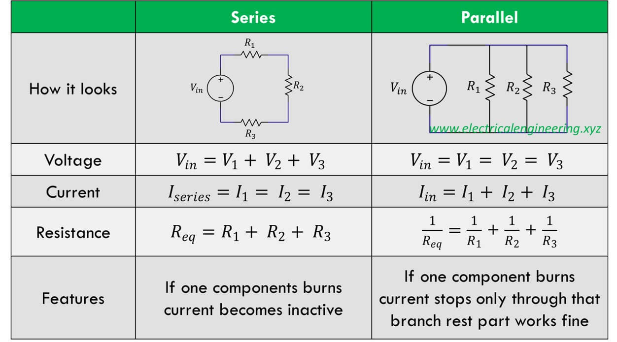
5 Differences Between Series And Parallel Circuits Important Question For Interview
Gg Ebooks
How To Solve A Parallel Circuit Easy Youtube
Circuits Current Potential Difference Resistance And Cells In Series And Parallel Circuits Conservation Of Charge


Comments
Post a Comment